APEX SYSTEM & EQUIPMENT CONTROLLERS
Supervisor Systems & Controllers
The BDF System Control is a distributed control system which uses the 7355X or 7360DDC Micro-controller as a host and individual micro-controller modules for dedicated control tasks. All modules are managed by a system controller microprocessor. Most of the control electronics are housed in a self standing control cabinet located at the end of the load station or adjacent to offset shroud. Satellite modules are located elsewhere in the Furnace system.
APEX Supervisory System
One APEX node controls up to 16 process tubes
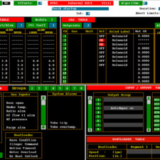
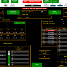
- APEX is a software application that provides a set of tools for automating wafer processing.
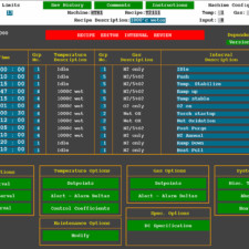
- Recipe Management
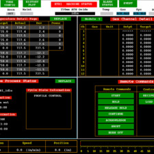
- Real Time Tube Status
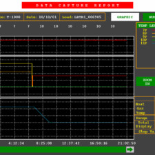
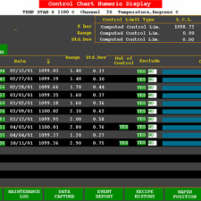
- Data Collection
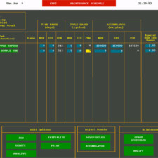
- Preventive Maintenance Management
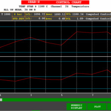
- Statistical Process Control (optional)
- Host Link Interface (optional)
- APEX Systems
- HP B2600 or C3600 Workstations
- HP-UX 10.20 Operating System
- Borland Interbase Database Management System
- Digi Etherlite Remote Multiplexer
- HP Printer/Plotter (PCL-5 / HPGL)
- APEX Communications
- Digi Etherlite Terminal Server
- Serial to TCP/IP Protocol over Network
- RS232 Serial Communication to Controller
- HSMS Direct Network Connection to Factory Host (optional) and Vertron III
- 10/100 BASE-T Ethernet utilizing TCP/IP across private network.
Model 7355X DDC
(operator panel, one per tube level)
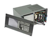
- 2.3 Version Firmware
- Menu driven from operator front panel.
- Communications port for upstream APEX Computer.
- System controller microprocessor.
- NICAD Battery Backup System
- Recipe control with the following features:
- 50 programmable time intervals
- 56 programmable inputs and outputs are available
- Automatic abort and hold capability
- Temperature control for up to six control/profile thermocouple pairs
- Auto profiling capability at operator request
- Set-point control for eight mass flow controllers
- Temperature and gas ramping capability
- Boatloader control
- Local storage/retrieval of up to three recipes while a fourth (duplicate) is operating
Boatloader Control Module
(one per tube level)
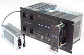
- Digital speed accuracy control to + 1% of set-point.
- End Travel position accuracy to ± 0.02” (0.51mm)
- Easy calibration.
- Manual override.
- Integrated EMS push-button and movement indicating light.
- On-board electronics for paddle lift and autodoor.
Gas Modules
(Mounted in Gas Cabinet Section)
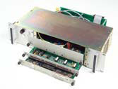
- Fully integrated with DDC.
- Interlocks with tube level alarms.
- Configured for process specific application.
VCVD
VCVD

Engineered for additional functionality, with a focus on improved In-situ diagnostics and ease of use, the VCVD Interface IIITM provides a three-fold increase in electrical accuracy in the leak rate measurement circuit. Combine this with an LCD readout, self-diagnostic capabilities and additional status monitoring LEDs, the VCVD Interface IIITM takes a major leap forward in VCVD processing.
- Key Benefits
- User selectable pre leak check outgas delay
- Verification of leak rate calibration by self test
- Full 60 second leak check
- Front panel accessible set up adjustments
- Specifications
- User selected leak rate trip point
- Range 1-30mTorr
- Increment 1mTorr
- Accuracy +/-2 mTorr
- User Selected outgas delay 0, 30, 60 Seconds
- Self Test – Integrity of leak check circuit verified over two 60-second test cycles
- Key Features
- Improved drift stability and accuracy
- Elimination of daughter boards
- Backward compatibility with our VCVD Interface II board
- LCD display of trip point and vacuum leak information
- Operational status provided by front panel LEDs
Temperature Control Module
(Mounted in Furnace Section)
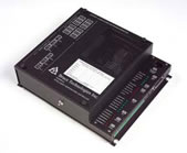
- Five dedicated control thermocouple channels and five profile thermocouple channels are available. One auxiliary channel is available for options requiring temperature control such as the external torch.
- Calibrated for “S” thermocouple types (Platinum vs. Platinum 10% Rhodium)
- Actual Spike and Overtemperature T/C feedback monitored continuously for immediate detection of T/C failure and if failure is detected, transfers control to a Back-up T/C
- System Calibration is not required
- Diagnostic Port provides access, using a PC or Terminal, for the following;
- Overtemperature trip setpoint is set to the heating element maximum operating temperature (is user adjustable).
- Temperature Control Setup and Calibration
- Overtemperature T/C readout
- Individual PID Power Contributions-Real-time Monitoring Capability
- T/C Failure Recovery Mode Status Monitoring Capability
- Alarm Status Monitoring Capability
- Alarm Output and LED indication if an Internal Power Supply is Out of Specification.
External Torch & Controller

- STARTUP TIMES
o FROM COLD TO IGNITION * 80 SEC
o FROM COLD TO MAX FLOW * 90 SEC
o WITH PREHEAT TO MAX FLOW * 30 SEC - PROGRAMMING
o 1 INTERVAL FOR BASIC PROGRAMMING
o H2 AND O2 SETPOINTS & SOLENOID REQUEST
o 3 INTERVALS FOR PREHEAT MODE - RELIABILITY
o PROJECTED MTBF > 5000 HRS
o TESTED > 8000 LAMP STARTS (650 HRS)
o “O” – RING MOUNTED INJECTOR FOR LEAK-TIGHT SEAL.
o SINGLE DESIGN INJECTOR FOR USE UP TO 20 SLM (TESTED UP TO 30 SLM)
o RAMP RATE UP TO 4 SLM/SEC
o NO QUARTZ SPUTTERING AFTER 650 HRS

